Thursday, December 29, 2011
Cad welding a tower ground system
I was asked by email to put this video back online. I made a short video showing how I connected a 2 inch wide copper strap to 16 - 8 foot ground rods forming my tower ground system. I still have all the step by step photos if anyone is interested in seeing those. (note you should wear a mask and not rely on the run for cover system)
Wednesday, December 28, 2011
New cubby holes for the boats

Picked up these used shelf units used at a great price. There are dividers in each one that are removable. A prefect place for these radios. The place is to hook them all up to run off the inverted "V". All I need is a switch, and make up a few jumpers.
Sunday, December 4, 2011
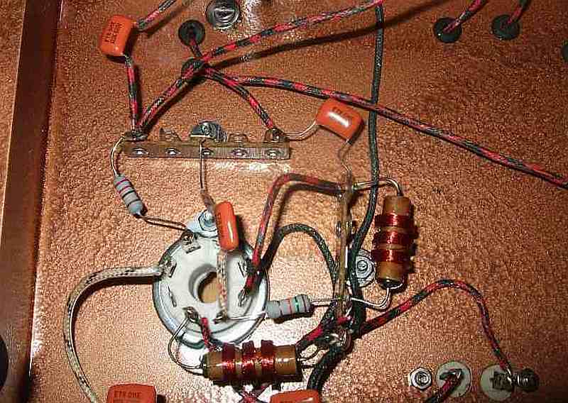
6L6 Transmitter Part 4 Finished
Finished up the 6L6 Transmitter project this week end. What a fun ride that was. A project like this IS a learning experience. This view shows the completed wired components looking toward the back.

This view is wired components looking toward the key jack. The Key jack ended up being faulty, so I had to swap it out with a new one. I could not figure out why I was not getting any out put from it. Elmer James found it. (good eye James) The jack had an extra part on it no doubt from someone Else's home brew project. I'll take that part off and use it for some thing else.

Finished 6L6 front side.

The back side showing the meter.

The finished pair on the bench. Power supply and Transmitter. I made a new set of Dials with bigger numbers, I think they look better.


Not too bad for an Amateur eh? A short video demo of the 6L6 Tune up.

This view is wired components looking toward the key jack. The Key jack ended up being faulty, so I had to swap it out with a new one. I could not figure out why I was not getting any out put from it. Elmer James found it. (good eye James) The jack had an extra part on it no doubt from someone Else's home brew project. I'll take that part off and use it for some thing else.
Finished 6L6 front side.
The back side showing the meter.

The finished pair on the bench. Power supply and Transmitter. I made a new set of Dials with bigger numbers, I think they look better.
Not too bad for an Amateur eh? A short video demo of the 6L6 Tune up.
Saturday, November 26, 2011
6L6 Transmitter part 3
Installed the hardware, and started wiring up the internal components.

The top side with the hard ware installed.

The front panel with meter and dial plates secured.

More to come.

The top side with the hard ware installed.

The front panel with meter and dial plates secured.

More to come.
Wednesday, November 23, 2011

Monday, November 21, 2011
6L6 Transmitter build Part 2
After getting the Dials all sorted out I started drilling holes and fitting the individual components. Anytime I build anything I like to dry fit all the parts. (old habit from 25 + years as a scientific glass blower)
I don't want to go back and re-drill holes after painting it.

This is the tool I used to drill the holes in the front panel a "Milwaukee ice" hole saw. You can buy them in the size you need or as a set. How do they work you ask? Very good, A+ in my book. It cut the 2" hole in the steel front panel easily, with a smooth finished edge. The aluminum chassis cuts were also good clean cuts.
Of course you must clamp it down before drilling.

All the parts dry fitted, adjustments made, I pulled off the protective paper from the chassis and cleaned it up with alcohol.

Nice and shiny!
Added a nice coat of primer, and I'll let it dry over night before I paint it the Copper Hammer-Tone color to match the power supply I built for it.

More to come.....
Thursday, November 17, 2011
Dial plates
Had a time finding knobs with dial faces for under e Pay prices. So I thought
about making my own. I got some copper sheet at the hobby store, and then
got some transparency paper to use with my laser printer.

I got the big iron out on high heat, with the copper plate covered with a sheet
of typing paper ironed the heck out of it.

It took a few trial and errors but I figured out how to do it. I cut out the
excess copper sheet and into the etch it went, for 20 minuets. A bit too long
per the instructions but I wanted a distressed look. After it came out of the
etch I rinsed and scrubbed off the printer ink.


 Then using a sharpie I colored it in and rubbed it with rubbing alcohol
to thin it out. It outlined the numbers just a little bit. I my go back with
printers ink to make it pop a little more.

While I was at it I made a badge for the chassis.


Well I did decide to black them in. what do you think? Clear coat over the top should seal them nicely.
Not too bad for a first timer eh.....
about making my own. I got some copper sheet at the hobby store, and then
got some transparency paper to use with my laser printer.
I got the big iron out on high heat, with the copper plate covered with a sheet
of typing paper ironed the heck out of it.

It took a few trial and errors but I figured out how to do it. I cut out the
excess copper sheet and into the etch it went, for 20 minuets. A bit too long
per the instructions but I wanted a distressed look. After it came out of the
etch I rinsed and scrubbed off the printer ink.


to thin it out. It outlined the numbers just a little bit. I my go back with
printers ink to make it pop a little more.

While I was at it I made a badge for the chassis.

Well I did decide to black them in. what do you think? Clear coat over the top should seal them nicely.
Not too bad for a first timer eh.....
Saturday, November 12, 2011
6L6 Transmitter
We now have enough of the parts to start the 6L6 transmitter project. I began laying out the front panel after cutting it down to size. I drilled the holes to attach it to the chassis. Along with the hole for the key jack. My small drill press does a great job on this kind of stuff.

I attached the 10 X 8 inch front panel with screws and inserted the key jack port. On the front panel I taped some paper 0-100 dial templates I made with Adobe Illustrator just to get a idea of the placement of the controls and ma meter.

Below I arranged the tuning capacitors, coil form socket, tube socket, and crystal socket. On the rear of the chassis I'll mark the positions for the terminal connection strip, SO 239 connector, and ground lug. More to come.....

Thursday, November 10, 2011
Christmas In November
Came home today after taking my son to the dentist. On the front porch was a box from my good friend and elmer for the 6L6 projects James Tobola - KC5LDO. This is what I found, a 10 watt 25K resistor, a 5U4GB tube and a 6L6 tube!

After installing the 10 watt 25K resistor (up from a 10 watt 20K) I measured 352.2 V DC. Up from 338 V DC I measured with the old resistor. Nice...
One of the thinks I like about this hobby is the willingness of hams to share knowledge, parts, and past experiences. If you can help someone out please do. I have in the past and will continue to do so like countless others in this great hobby.
Thanks again James!
Sunday, October 30, 2011
Power supply using a 5U4GB tube
For my Fall / Winter project this year I thought I would build from scratch a 6L6 transmitter and power supply. I'll start with the power supply using a 5U4G tube.

I started out with a slate gray metal chassis, and started laying out component placement.

I used a 10 X 6 chassis, drilled all the holes and checked for screw alignment. You don't want to be drilling after you paint it. ( although I've been there done that) I Dremel tool is great for any slight misalignment, or touching up a hole that is a little too small.

I wanted to try the Hammer Tone paint, so I bought a can of a copper colored paint. Isn't that paint nice! Installed the grommets for the wires going through from the top.

I installed the connection block and fuse. The other hole will be for the incoming AC power cord.

Installed the tube socket for the 5U4GB tube, power switch, and indicator lamp. I'll let the paint cure a few more days before I turn it over and finish installing the smaller components.

A view of the under side. Wiring is a little goofy because I used pieces that I had laying around. Capacitor are 10 MF, 33 MF at 450V and a 10 watt 20K resistor.

All finished, powered on and works fine. The red lamp is a wee bit bright. I my add a small resister to dim it a bit. Output is 338 V DC, and 6.7 V on the terminals.

I started out with a slate gray metal chassis, and started laying out component placement.

I used a 10 X 6 chassis, drilled all the holes and checked for screw alignment. You don't want to be drilling after you paint it. ( although I've been there done that) I Dremel tool is great for any slight misalignment, or touching up a hole that is a little too small.

I wanted to try the Hammer Tone paint, so I bought a can of a copper colored paint. Isn't that paint nice! Installed the grommets for the wires going through from the top.

I installed the connection block and fuse. The other hole will be for the incoming AC power cord.
Installed the tube socket for the 5U4GB tube, power switch, and indicator lamp. I'll let the paint cure a few more days before I turn it over and finish installing the smaller components.

A view of the under side. Wiring is a little goofy because I used pieces that I had laying around. Capacitor are 10 MF, 33 MF at 450V and a 10 watt 20K resistor.

All finished, powered on and works fine. The red lamp is a wee bit bright. I my add a small resister to dim it a bit. Output is 338 V DC, and 6.7 V on the terminals.
Thursday, September 22, 2011
Anchors away!
I rearranged the shack. Set up all my older tube equipment that I have restored on the bench. Not at all a bad little collection. My wife said I am a radio hoarder. I showed her a shack that had hundreds of older transmitters and receivers. She asked if that was my dream shack......


Wednesday, September 21, 2011
Regulated power supply
You might remember the computer power supply I converted to a DC power supply. Well in a word It sucked...
Always not the right voltage for what I needed. So while watching Ham Nation episode 17 I saw George build one from scratch out of junk box parts. This is just what I wanted. A regulated power supply where I could control the voltage to my exact needs.
 Here is a peek at the insides before I stuck everything down. The large heat sink came from the old computer power supply, and since the project box was big I left it intact. Perf board ( I used point to point construction on the back side to wire it together) Its not very complicated a 4700 µf cap, voltage regulator, full wave bridge rectifier, fuse, plus a few other small caps.

The power supply came from Radio Shack 12 bucks...

 I can control the voltage from 1.25 V DC to 35. V DC . I added an LED and powered it from the AC side of the circuit buffered with a 10KΩ resistor.
Always not the right voltage for what I needed. So while watching Ham Nation episode 17 I saw George build one from scratch out of junk box parts. This is just what I wanted. A regulated power supply where I could control the voltage to my exact needs.


The power supply came from Radio Shack 12 bucks...


Saturday, September 17, 2011
W5SJZ-11 Balloon
Made a contact with Robert / WE5T using my Kenwood HT and arrow antenna with 5 watts. The balloon was at 68199 FT. Pictures are from Google APRS.FI

This is the flight path. The start was at the municipal airport in Hillsboro, Texas. I think the highest recorded altitude was a little over 80, 000 feet.

The last reported packet was at 32,388 feet. Never heard the 10 meter beacon. A fun diversion from a normal Saturday morning.

This is the flight path. The start was at the municipal airport in Hillsboro, Texas. I think the highest recorded altitude was a little over 80, 000 feet.

The last reported packet was at 32,388 feet. Never heard the 10 meter beacon. A fun diversion from a normal Saturday morning.
Thursday, September 8, 2011
Heathkit HG-10B VFO

I picked up a Heathkit HG-10B VFO. I modified it to use with the Drake 2-NT. The modifications are floating around the internet if you do a search for it. Roy Vickers KF5YU's original instructions are very easy to follow. BEWARE high voltages under the hood!

Just make sure your cables wires match on each end. I used the VFO's wire, and removed the 8 pin plug. Added a male and female Molex type plug. Any four wire type plug will work. Pull the +250VDC and the 6.5VAC from the Drake 2-NT with the other half of the connector.
Tested it out today in a dummy load and it works GREAT! Saving the crystals for the Knight Kit T-60.

Thursday, September 1, 2011
Arrisat 1

I caught Arrisat 1 on a nearly overhead pass this last week. I used my trusty Kenwood HT, an arrow antenna, and a small camera with a video record option. (a cell phone with video works also) Go to the Amsat web site put in your location and you can get up to the next 50 passes for your location.

This worked really well. I got an SSTV image, the voice telemetry, and the secret password in one of the 24 different language greetings.

Here is one of the certificates for sending in a report. That's all there is to it , simple easy.
Sunday, August 21, 2011
Drake 2-C
Picked up a Drake 2-C reciever to match my Drake 2 -NT transmitter. Its a little rough but I think it will be fine.

The face of the reciever is very good for its age. The copper chassis is anything but. lots of little spots all over.

A few caps of the paper variety....

Top side. This one will take a little time I am sure.

The face of the reciever is very good for its age. The copper chassis is anything but. lots of little spots all over.

A few caps of the paper variety....

Top side. This one will take a little time I am sure.
Subscribe to:
Posts (Atom)