Showing posts with label amatuer radio. Show all posts

Friday, April 27, 2012

A.M. Passive Antenna Loop

Here is an antenna for the A.M. band I built out of a recycled cardboard tube, some wire and an air variable capacitor. The loop is 16 3/8 tall with 24 turns of 20 gauge wire about an 1 in wide. So if my math is right I have about 103 feet of wire.


Not a real work of art, but it does work fine. I sprayed it with clear lacquer to keep the wire in place on the cardboard tube. I used tape to hold the wire in position (close wound) while I sprayed it. One note here the lacquer I used melted the tape in some places so I hit in between, let it dry then took off the tape to finish it. The hot-glue gun was used to fasten it to the wooden plaque.


A short demo of the loop in action. I found a very hard to hear signal down in the noise and tuned up the loop to hear it (them). There were actually two stations that came in. I'll have to listen to them to see where they are broadcasting from. Anyhow I am pleased with the result.

Saturday, April 21, 2012

Twinplex Regenerative Receiver part 5 done deal

The Twinplex Regenerative Receiver has taught me a lot. It is amazing to think about all the experimentation that went on years ago to get to where we are today in radio.

I wound a coil for the upper part of the AM band. 87 or so turns to start, then removing 3 at a time until I hit where I wanted. I ended up with 76 to 16 (tickler) and may still take a few off the tickler coil to find the effect there. It is kind of narrow banded I think 920 to 1380.


  A side view Of the Twinplex with the AM (lower end) coil.


Front view of the Twinplex with the knob indicator and control plates I made for it. My wife says I should find copper screws or rivets to match.


A special thanks to my mentor on this project.

Tuesday, April 17, 2012

Twinplex on AM


A short video of the Twinplex working on the AM band. Listening to Baseball will be a hoot on this radio...


I found a 100 MMF capacitor in one of my coil forms. I wonder what this coil was used for in the past.

Twinplex Regenerative Receiver part 4

I ran a test with the receiver with a 9 to 3 coil and picked up this beacon station WLO. I wanted to make sure everything worked before mounting the front panel for the final time. I also picked up several religious broadcasts so I figure it must have been up in the 8500 over 40 meters anyhow.


I also built a 40 meter coil 9 to 2 turns. I listened to several QSOs and what sounded like PSK so I am happy with that coil.


 I mounted the knobs, and bolted everything down good. I still had a couple of hours to kill so I decided to try to build an AM coil. I found an AM loop stick that came in one of my son's old electronics kits. After mounting it inside one of my coil forms, I added 2 loops for a tickler coil. Worked first try! I found stations from 620 up to 770 so far. but it works surprisingly well.


The AM loop stick is laying on its side in the coil form. I do not know if that causes a problem or not. I'll try centering it to see later.

Monday, April 16, 2012

Belton Hamfest

Went down to Belton for the hamfest last weekend and had a blast. Scored some real deals on parts I was looking for, and some I wasn't. If you get a chance go down to Belton or any ham swap-meet. It is is good time plus you can get parts for a LOT less than online sellers.

I meet James KC5LDO for an eyeball QSO and a tour of his shack, while my wife and his chatted for a while. ( I think this was the highlight of the trip for my wife, she gets dragged along and usually has to fend for herself.)

I had a chance to look over some of the great projects he had built. I got a first hand demonstration on how his Regenerative Receiver works. That is one hot little receiver. With only a short antenna, it pulled in many stations. Home brewing at its finest! We talked radios, antennas, and all the things you expect radio nuts to discuss. I showed James what I had so far with my own Regenerative Receiver and of course he spotted right off a problem I had been working on for the last few days.

Well it wasn't long before I had to get back on the road ( had to work that night).  James loaded me up with a sack full of parts, (thanks again James) we all said our goodbys and hit the road...

Oh yea there was this UFO thing we saw on the way back :)


You just never know what you might see on the road...

Saturday, April 7, 2012

Twinplex Regenerative Receiver Part 3

Got a little more done today. The chassis paint came out great, so we have this process down. A deep Emerald green.


Installed the Hardware for the backside of the receiver. Broke down and bought a box of screws and nuts plus washers. A lot cheaper in the long run. Here is a picture of the backside with the parts installed.


On to the underside of the chassis. The filament transformer and audio transformer are installed. I also put in a few caps and resistors.


Back to the top side of the chassis now. I mounted the Band-set and Band-spread capacitors. Using the big knobs made putting plastic spacers underneath a must, but they are secure. Added the binding posts for the B+  voltage.


More to come....

Friday, March 30, 2012

Twinplex Regenerative Receiver part 2

Today I got  the chores out of the way early and started punching holes in the back of the chassis. There are quite a few for all the parts that are going to be installed back there. I try to group the power cord, fuse, switch, and transformer close to allow the shortest wire runs possible. If you think ahead about where everything goes you won't have to go back and touch up paint. (not that I have ever had to do that... Ahem cough cough)

 Here is a view of the chassis with the holes drilled today. Somehow I lost my socket for the Hammerland 6 pin coil form. So here I go on a hunt for another...

The Green Hammer-tone paint came out fine on the chassis front panel. Letting it sit in the sun before spraying seems to help the process along. In the background you can see the power supply for the 6L6.
More to come....

Thursday, March 29, 2012

Twinplex Regenerative Receiver Build

I started today on the Twinplex Regenerative Receiver. The parts have piling up since my friend James told me he found a good receiver design to build. He has gleaned great results with his and says it is a hot little receiver. (good enough for me)


Here is the box  O' Parts. Those Big knobs are vintage NOS I picked up very cheap. I did buy some more of the cloth covered wire from  http://enginebarn.myshopify.com/   
No affiliation. I just like the product.


After some tedious measuring and layout, I finally found a layout I liked. Let the drilling begin....

 The front panel holes are in place, now for the chassis front hole placement. My drill press is just big enough to be able to mark (with the drill bit) the chassis with the front panel still attached. This means all the holes will match up perfectly.

 Here is a view of the parts for the front panel dry fitted to the chassis. Everything lines up perfectly so the front panel is now ready to be painted. The paint of choice is going to be hammer-tone green. Green you say? Yep green...(Is it starting to look like a radio yet?)
 More to come...

Friday, March 23, 2012

Old US Army Morse Code training film.


Old training video.

Thunderstorm, Rain and Morse Code from Bug (MP3)

Thunderstorm Rain And Morse Code

In the MP3 link above I really like the mix.Here is the story that goes with it:

In the middle 1980s, former United States Coast Guard Radioman and well known radio amateur, Edward A. McCarthy was tuning the 7.0 MHz amateur radio bands at his amateur radio station in Florida when he came upon a conversation between two amateurs using continuous wave (CW) Morse radiotelegraphy. Since a tape recorder was nearby, he decided to record the conversation between David J. Ring, Jr., N1EA/MM (Maritime Mobile) who was sailing as Radio Officer in the Merchant Marine on the coast wise tanker "SS KING" run by American Heavy Lift Shipping, Inc. of Houston, TX. The SS KING was in the middle of the Gulf of Mexico having sailed from Corpus Christi, Texas two days prior and another local radio amateur who was getting on the air after a long absence.

Mr. McCarthy, W1YT sent this recording directly to the "SS KING" where Mr. Ring was so overjoyed at the quality, he decided to improve on it by making a recording of storm and rain sounds and mixing the Morse code together with it.

Friday, February 24, 2012

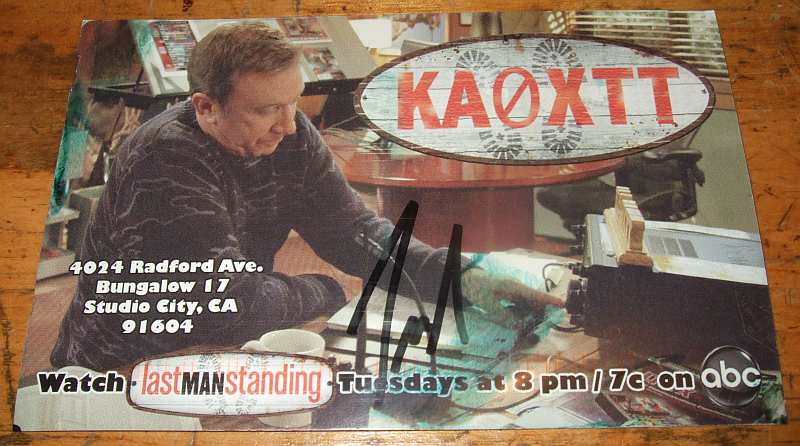
I received my Last man standing "QSL" card

I watch Last Man Standing on TV with Tim Allen. Tim's character is KA0XTT. They have a small station set up that actually works since the director is an extra class HAM. Anyhow if you send them your QSL card Tim Allen will autograph "his card" and send it to you. (NO SASE NEEDED!) It is not a real call, they made it up but it does shows up on QRZ. The call is supposed to be a Colorado call and the XTT part is an inside joke that means X  T im T aylor from the old Home Improvement TV show. Just a "for fun" autographed card. Who knows your card may end up on his shack wall... 

Thursday, December 29, 2011

Cad welding a tower ground system


I was asked by email to put this video back online. I made a short video showing how I connected a 2 inch wide copper strap to 16 - 8 foot ground rods forming my tower ground system. I still have all the step by step photos if anyone is interested in seeing those. (note you should wear a mask and not rely on the run for cover system)

Wednesday, December 28, 2011

New cubby holes for the boats


Picked up these used shelf units used at a great price. There are dividers in each one that are removable. A prefect place for these radios. The place is to hook them all up to run off the inverted "V". All I need is a switch, and make up a few jumpers.

Sunday, December 4, 2011

6L6 Transmitter Part 4 Finished

Finished up the 6L6 Transmitter project this week end. What a fun ride that was. A project like this IS a learning experience. This view shows the completed wired components looking toward the back.


This view is wired  components looking toward the key jack. The Key jack ended up being faulty, so I had to swap it out with a new one. I could not figure out why I was not getting any out put from it. Elmer James found it. (good eye James) The jack had an extra part on it no doubt from someone Else's home brew project. I'll take that part off and use it for some thing else.


Finished 6L6 front side.


The back side showing the meter.


The finished pair on the bench. Power supply and Transmitter. I made a new set of Dials with bigger numbers, I think they look better.


Not too bad for an Amateur eh? A short video demo of the 6L6 Tune up.

Saturday, November 26, 2011

6L6 Transmitter part 3

Installed the hardware, and started wiring up the internal components.


 The top side with the hard ware installed.


The front panel with meter and dial plates secured.


More to come.

Wednesday, November 23, 2011

Monday, November 21, 2011

6L6 Transmitter build Part 2

After getting the Dials all sorted out I started drilling holes and fitting the individual components. Anytime I build anything I like to dry fit all the parts. (old habit from 25 + years as a scientific glass blower)
I don't want to go back and re-drill holes after painting it.


This is the tool I used to drill the holes in the front panel a "Milwaukee ice" hole saw. You can buy them in the size you need or as a set. How do they work you ask? Very good, A+ in my book. It cut the 2" hole in the steel front panel easily, with a smooth finished edge. The aluminum chassis cuts were also good clean cuts.
Of course you must clamp it down before drilling. 


All the parts dry fitted, adjustments made, I pulled off the protective paper from the chassis and cleaned it up with alcohol.


Nice and shiny!
Added a  nice coat of primer, and I'll let it dry over night before I paint it the Copper Hammer-Tone color to match the power supply I built for it.


More to come.....

Thursday, November 17, 2011

Dial plates

Had a time finding knobs with dial faces for under e Pay prices. So I thought
about making my own. I got some copper sheet at the hobby store, and then
got some transparency paper to use with my laser printer.


I got the big iron out on high heat, with the copper plate covered with a sheet
of typing paper ironed the heck out of it.


It took a few trial and errors but I figured out how to do it. I cut out the
excess copper sheet and into the etch it went, for 20 minuets. A bit too long
per the instructions but I wanted a distressed look. After it came out of the
etch I rinsed and scrubbed off the printer ink.


Then using a sharpie I colored it in and rubbed it with rubbing alcohol
to thin it out. It outlined the numbers just a little bit. I my go back with
printers ink to make it pop a little more.


While I was at it I made a badge for the chassis.


Well I did decide to black them in. what do you think? Clear coat over the top should seal them nicely.
Not too bad for a first timer eh.....

Saturday, November 12, 2011

6L6 Transmitter

We now have enough of the parts to start the 6L6 transmitter project. I began laying out the front panel after cutting it down to size. I drilled the holes to attach it to the chassis. Along with the hole for the key jack. My small drill press does a great job on this kind of stuff.


 I attached the 10 X 8 inch front panel with screws and inserted the key jack port. On the front panel I taped some paper 0-100 dial  templates I made with Adobe Illustrator just to get a idea of the placement of the controls and ma meter.   


Below I arranged the tuning capacitors, coil form socket, tube socket, and crystal socket. On the rear of the chassis I'll mark the positions for the terminal connection strip, SO 239 connector, and ground lug. More to come.....


Thursday, November 10, 2011

Christmas In November

Came home today after taking my son to the dentist. On the front porch was a box from my good friend and elmer for the 6L6 projects James Tobola - KC5LDO. This is what I found, a 10 watt 25K resistor, a 5U4GB tube and a 6L6 tube!


After installing the 10 watt 25K resistor (up from a 10 watt 20K) I measured 352.2 V DC. Up from 338 V DC I measured with the old resistor. Nice...

One of the thinks I like about this hobby is the willingness of hams to share knowledge, parts, and past experiences. If you can help someone out please do. I have in the past and will continue to do so like countless others in this great hobby.

Thanks again James!